Section outline

    • The Wall Style Definition tab

    • KEY FEATURES

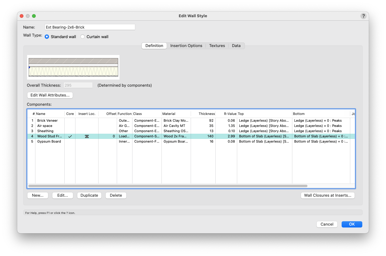
      At the top of the dialog, you will see a Top/Plan diagram of your wall style, showing any components you may have added and a small arrow indicating the direction. This arrow can be seen in the drawing on an individually selected wall. This arrow indicating direction is important because, when looking in the direction of the arrow, Vectorworks considers the left side of the arrow and, thus, the left side of the wall to be the outside of the wall. This left-side-is-outside orientation is critical for a wall's interactions with inserts like doors and windows.
    • ⓘ If you have accidentally drawn a wall in the wrong direction, select the wall and click Reverse Sides in the Object Info palette.
    • Overall Thickness: If your wall has components, then this field will be automatically calculated (providing the product of the wall component thicknesses) and greyed. If your wall does not have components, then you enter a specific value for the wall's overall thickness in this field. (For unstyled walls, you can adjust this value per wall via the Object Info palette; however, the overall thickness will change relative to the wall's centerline.)

      Edit Wall Attributes

      Wall Attributes: The parameters of this dialog allow you to set fill and pen attributes for the wall object. Click the Make all Attributes by Class button to defer to the slab object's class settings.

      Attributes Below Cut Plane: This dropdown is used to select an alternative class that determines the wall's attributes when the wall's height is below the host design layer's cut plane. For this feature to be active, the host design layer's Enable Cut Plane at Layer Elevation checkbox must be checked; see the Edit Design Layers dialog.

      Components: You can add, edit, duplicate, delete, and sort your components here. You can also edit the components' settings directly by clicking into the rows' cells or by highlighting one or more rows and clicking the Edit button at the bottom of the dialog. (Note: Walls do not require a component to function.)

      Wall Closures at Inserts: This button at the bottom right of the dialog opens the Wall Closures at Inserts dialog, where you can create and edit wall closure names and their effects: Profile Shapes, Profile Offsets, and Wrappings.
    • ⓘ If you have wall components, be sure to designate which one is the Core component: Click in the component's row beneath the Core column. The Core component is typically the primary structural component of the wall assembly.

    • ADDING COMPONENTS

      Click New to add components to your wall.

      Wall Component Settings

      Definition: Set the component's defining features. A new component needs a Name and Thickness at minimum. If a Material is selected, the component can automatically derive its Fill, Texture, and Lambda value from that Material.

      Fill, Texture, Left Pen, and Right Pen: The graphic appearance of the component can be
      • set by Style (set Material to None, click Remove by Class Settings, and edit the fields manually),
      • set by Class (select a Class from the Definition dropdown, set Material to None, and click Make all Attributes By Class), or
      • set by Material (select a Material in the Definition field; Left Pen and Right Pen must be set by Class or manually by Style).
      Note: When a Material is assigned to a component, the Material's attributes override the Fill and Texture. However, you can still change to a different Texture while keeping the Material active.

      Component Top and Component Bottom: A component's top and bottom bounds can be set as "Relative to wall" or "Relative to story." When stories exist with active level types, a specific level type can be selected from the dropdown. Offset values for component top and bottom bounds may also be manually entered. 

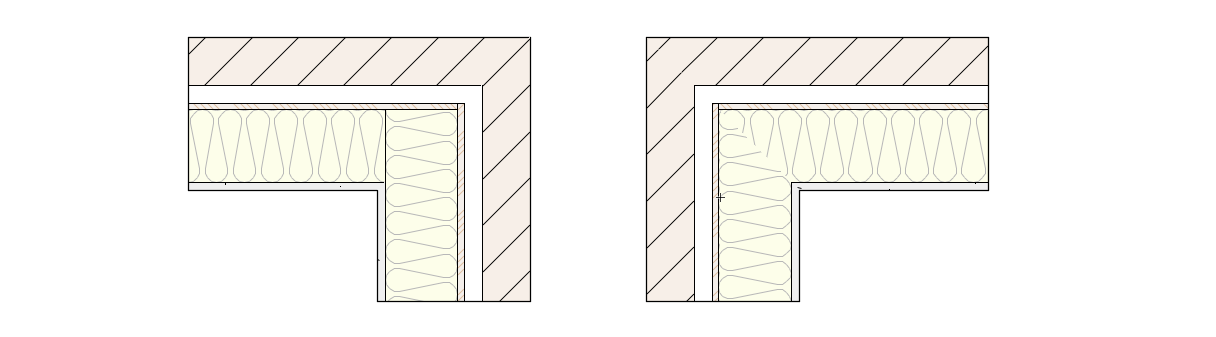
      Always auto join in Capped Join mode: This will cap (draw a dividing line at) the components orthogonally relative to the wall's length at the join rather than chamfer diagonally (without a dividing line), as seen below.

      A wall corner with Always auto join in Capped Join mode checked and another without for comparison

      Master Snap Points: These checkboxes allow you to activate a snapping priority for the left and/or right side of the component. This is usually done for structural components to make dimensioning easier.