THE WINDOW TOOL SETTINGS
Completion requirements
Go through the activity to the end
2D VISUALISATION
The 2D Visualisation pane contains parameters for the visibility and attributes of window components as seen in Top/Plan views. Several of this pane's key features are described below, but for a more comprehensive breakdown, be sure to visit the Help page.
Key Features
Draw wall lines: When this option is checked, lines depicting the continuation of the wall above the opening are displayed. By default, this is unchecked, so lines are not shown extending across the opening. Alternatively, these lines can be shown by setting the Header class to visible when needed.

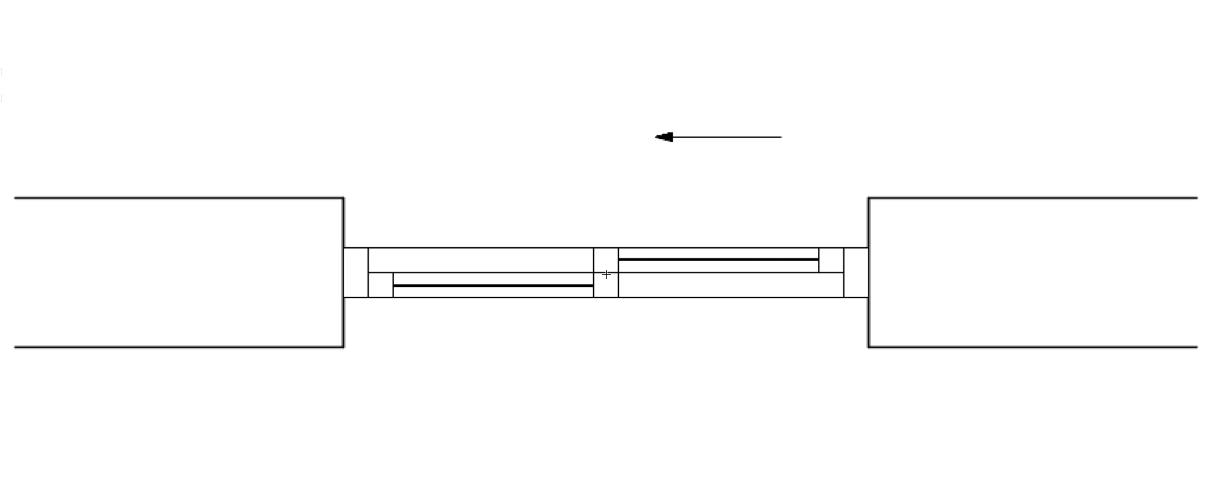
Show operation direction: When this option is checked, an arrow appears indicating the window's operation direction in Top/Plan views. However, this option only applies to certain window configurations.
SET ATTRIBUTES BY
Object: This choice will apply the pen thickness and line type of the window object's pen settings to all window components, whether the window object's pen settings are determined by settings in the Attributes palette or prescribed by the window's class definition.
Line Style: This choice lets you set the pen thickness and line type individually for each window component.
Class: This choice allows you to defer the settings for pen thickness and line type—component by component—to a specific class.
ⓘ When Class is chosen for the Set Attributes By parameter, components set to the default <Window Class> option will defer their pen thickness and line type settings to the window object's assigned class (as seen in the Object Info palette when the window is selected).
Visibility Classes: These classes control the visibility of window elements that are commonly hidden. In other words, these are the classes you will use to make window elements—Sill, Header, 2D Loci, and Alternate Path—visible, invisible, or gray. You may change their default class names to align with your specific class naming standards.